
The Mobile Industry Processor Interface Alliance (MIPI) developed a serial communication protocol known as the Display Serial Interface or DSI
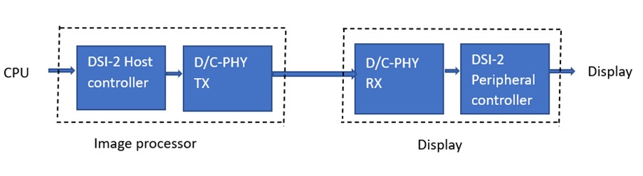
MIPI DSI2 stands for high-speed Display Serial Interface between a host processor and a display module.
The DSI2 interface enables manufacturers to integrate displays to achieve high performance, low power, and low electromagnetic interference (EMI) while reducing pin count and maintaining compatibility across different vendors
The MIPI display serial interface requires fewer pin connections while maintaining the same level of performance.
DSI2 supports
Only one PHY can be configured at a time of transmission.
Major difference between C-PHY and D-PHY are clock lane and data lane.
| D-PHY | C-PHY | |
|---|---|---|
| Packet Structures | Same packet structure for High Speed mode and Escape Mode operations | Different packet structure for High Speed mode and Escape Mode operations |
| Distribution or Merging | By bytes | By 16-bit words |
| Serialization in High Speed Mode | Serialization with a forward clock | 3-phase encoding and serialization |
| Clock in High Speed Mode | Send or receive clock from the Clock Lane | Embed or recover clock from the Data Lane(s) |
| Continuous Clock Behavior | Applicable on the Clock Lane | Applicable on one of the Data Lane(s) |
| EoTp Packet | Applicable | Not applicable |
| Detect and Correct Errors in a Packet Header Transferred in High Speed Mode | Use ECC | Use packet header checksum, SSDC and packet header replicate |
| EoT Sync Error | Applicable | Not applicable |
| Deskew Calibration | Applicable | Not applicable |
| Minimum PPI Interface Width | 8 bits | 16 bits |
| Data Rate | 500Mbps | 100Mbps |